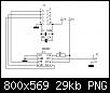
Manchmal möchte man Spannungen steuern/regeln ohne großartig mechanische Potis zum Einsatz zu bringen.
Im folgenden einmal Schaltplan und der Code zu Ansteuerung. Leider findet man den AD8400 nur in SOIC-Form was es ein wenig
schwierig macht es zum direkten basteln zu nutzen.
weitere digi Pots:
AD5260
UB Digitalteil 0-5V /15V single supply, dualsupply ±5,5V
UB ResistorPins 0-VCC
AD840x
UB Digitalteil 0-5V
UB ResistorPins 0-5V
X9C
UB Digitalteil 0-5V
UB ResistorPins ±5,5V
Code:
.include "m8def.inc"	;Atmega8

.def temp0 = r16 	;
.def temp1 = r17 	;
.def temp2 = r18
.def temp3 = r19 	;
.def temp4 = r20
.def cnt   = r21

.equ	Poti0		=	$0060

;*********Digitales Poti AD8400
.equ	PotPort		=	PortB
.equ	Potddr		=	ddrB
.equ	PotPin		=	PinB

.equ	PotCS		=	1				;Takterzeugung
.equ	PotDat		=	3				;Daten
.equ	PotCl		=	5				;Chip Select

;***************************Einsprungadressen***********************
.cseg
.org $0000
	rjmp	stack
.org $0001			;1
	reti;rjmp	INT_0
.org $0002			;2
	reti;rjmp	INT_1
.org $0003			;3
	reti;rjmp	INT_OC2
.org $0004			;4
	reti;rjmp	INT_OVF2
.org $0005			;5
	reti;rjmp	INT_ICP1
.org $0006			;6
	reti;rjmp	INT_OC1A
.org $0007			;7
	reti;rjmp	INT_OC1B
.org $0008			;8
	reti;rjmp	INT_OVF1
.org $0009			;9
	reti;	rjmp	INT_OVF0
	reti		;a keine SPI Routinen
.org $000b		;b
	reti;rjmp	INT_URXC
.org $000c		;c
	reti;rjmp	INT_UDRE
.org $000d		;d
	reti;rjmp	INT_UTXC
.org $000e		;e
	reti;rjmp	adc_rdy
.org $000f		;f
	reti;rjmp	eeprom_rdy
.org $0010		;10
	reti;rjmp	ac_int
	reti		;11	keine 2wireRoutinen
	reti		;12 keine SPMRoutinen

;***************************Init mit allem drumdran*****************
stack:       	ldi 		temp1,high(ramend)  ;Stackpointer festlegen
	        out 		sph, temp1
		ldi 		temp1,low(ramend)   ;Stackpointer festlegen
                out 		spl, temp1
		rcall		Pot_AD8400_init

start:  	sbic		pinb,2
		rcall		poti_plus

		sbic		pinb,4
		rcall		poti_minus

		rjmp		start

;*************************weitere*includedata***********************
.include "zeitschleifen.asm"
.include "AD8400.asm"
hier die Include für das Poti selbst
Code:
;********Digitales Potentiometer Ansteuerung**************
;
;	B1  = 1---8 = A1
;	GND = 2---7 = W1
;	!=CS= 3---6 = VCC
;	SDI = 4---5 = CLK
;
/*
;*********Digitales Poti AD8400
.equ	PotPort		=	Portb
.equ	Potddr		=	ddrB
.equ	PotPin		=	PinB

.equ	PotCS		=	0				;Takterzeugung
.equ	PotDat		=	2				;Daten
.equ	PotCl		=	4				;Chip Select
*/

;****************Pins setzen*******************************
Pot_AD8400_init:
		cbi			PotPort,PotCl		;Cl
		cbi			PotPort,PotDat		;Dat
		sbi			PotPort,PotCS		;CS setzen auf Port = pullup
		sbi			Potddr,PotCl 		;
		sbi			Potddr,PotDat		;
		cbi			Potddr,PotCS		;ddr setzen
		rcall	        	AD8400_daten		;und einmal alles auf 0 setzen weil sonst 128/256 ist, STD siehe Anlage AN308
		ret

;********plus
poti_plus:
		rcall	        	wait150ms
		lds			temp0,Poti0
		inc			temp0
		sts			Poti0,temp0
		rcall	          	AD8400_Daten
		ret

;********minus
poti_minus:
		rcall		        wait150ms
		lds			temp0,Poti0
		dec			temp0
		sts			Poti0,temp0
		rcall		        AD8400_Daten
		ret

;*************CLK erzeugen
AD8400_clk:
		sbi			PotPort,PotCl
		nop
		nop
		cbi			PotPort,PotCl
		ret

;************aktivieren
AD8400_aktiv:
		sbi			Potddr,PotCS		;pullup deaktivieren lowlevel
		cbi			PotPort,PotCS
		ret

;***********deaktivieren
AD8400_deaktiv:							;pullup aktivieren highlevel
		cbi			Potddr,PotCS
		sbi			PotPort,PotCS
		ret

;**************Daten Senden aus XH:L = 10bit
AD8400_Daten:
		clr			cnt
		rcall		        AD8400_aktiv		;chip aktivieren
		clr			xh				;
		lds			xl,Poti0		;hier sind die Daten
AD8400_Daten2:
		sbrc		        xh,1			;10tes Bit abfragen
		sbi			PotPort,PotDat	        ;1 setzen
		sbrs		        xh,1			;10tes Bit abfragen
		cbi			PotPort,PotDat	        ;0 setzen
		rcall		        AD8400_clk		;Clocken
		lsl			xl
		rol			xh			;shiften
		inc			cnt			;+1
		cpi			cnt,$0a			;=10?
		brne		        AD8400_Daten2		;spring wenn !=
		rcall	        	AD8400_deaktiv		;CHIP deaktivieren
		ret
Viel Erfolg
avr_racer


 Zitieren

Lesezeichen